Chapter 10. Reactor Coolant Pumps and Pump Seals
The DBNPP RCPs are large pieces of equipment, roughly 25 feet tall with a motor running on 13,800 volts. The motor is rated at 9000 Hp at NOPT. These pumps impart so much energy into the coolant water that they pump, that running them is used to heat the Reactor Coolant System up to operating conditions for plant startup. When running in cold water conditions the motor generates about 10,000 Hp. It has its own support systems and special design features. The motor has a large inertial flywheel at the top to provide a coast down of flow on power loss and directly below that is a double acting Kingsbury type thrust bearing. The external circumference of the flywheel has teeth grooves machined in it and the motor frame has a spring loaded pawl which will drop into a flywheel groove to prevent reverse rotation of the pump during asymmetrical RCP combinations where the Reactor Coolant System flow through an idle pump would be backwards. The thrust bearing has its own pumped oil system complete with a cooling water system (external), low pressure and high temperature alarms, and a lift oil feature for starting, etc. The whole weight of the RCP and motor basically hangs off the thrust bearing which provides vertical stability for the variable opposing forces on the pump. The Reactor Coolant System pressure is trying to push the pump up, out of the system, while the pumping action of the impellor is trying to pull the pump down. Both the pump and motor have radial bearings, with the pump radial bearing being water lubricated, supplied from either the Seal Injection (SI) flow when available or Reactor Coolant water when SI is not available. Since at full power the pump is pumping very hot fluid (over 550 F), the pump shaft seal and motor is protected from the effects of this heat conducting up the shaft by means of a thermal barrier (large mass of metal) that has externally supplied cooling water. The pump can be externally monitored from the Control Room by both acoustical monitors and displacement vibration monitors; plant computer generated bearing temperature alarms, oil pressure alarms, cooling water alarms, etc.
The most critical component of the RCP is the shaft seal as it provides the barrier between the 2000 PSI plus pressure in the Reactor Coolant System and the Containment atmosphere. For those familiar with a standard pump rotating mechanical seal used in low pressure applications, this one is slightly different. First, it is actually three seals in series with each seal containing a rotating face and a stationary face. Second, it is not designed to be zero leakage across each seal face, as a small amount of leakage is used to lubricate and cool the seal faces. This design leakage in combination with a controlled bleed-off via a Seal Return flow enables each stage of the seal to drop one-third of the Reactor Coolant System pressure between the Reactor Coolant System and the Containment atmosphere. Thus the delta-P across each seal face at NOPT is nominally about 700 PSI. However by design each seal is capable of taking the total 2000 PSI pressure drop should the other two seals fail. Its ability to do this long-term is entirely dependent on its condition prior to the failure of the other two seal stages. The below pictures are functional cartoons to used to illustrate how the seal functions.
Note: These pictures were taken from the NRC Training web site link: Source
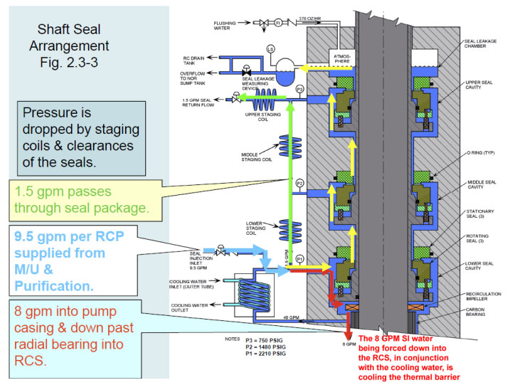
The notes on the above drawing explain what is functionally going on. The staging coil is functionally an orifice, engineered to provide the 1.5 GPM flow rate at a nominal 700 PSI differential pressure. Note that there are 2 flow paths provided from each lower seal stage cavity to its upper seal stage cavity. One through the staging coil and another seal face leakage. The cooling water heat exchanger that the SI flow is going through is actually physically wrapped around the pump thermal barrier below (area of the “carbon bearing”). The top “seal leakage collection chamber” area is called the “standpipe” and is open to the Containment pressure. The flushing water is provided to prevent boric acid buildup in the standpipe. The “seal leakage measuring device” was an add-on to our original design; don’t know what is there now but we called the original add-on the “drinking bird”. Yup, that’s how it worked; dump the bucket, count the dumps. The isolation valves shown on the SI and SR lines are the same valves we were busy opening early in the narrative. They were automatically closed by the SFAS signal.
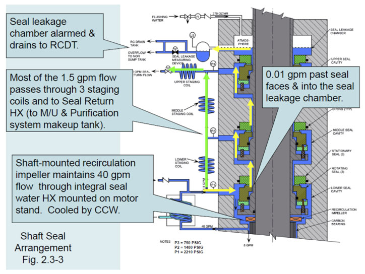
Same drawing above with more information provided.
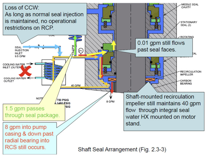
The above drawing shows the seal with a loss the external cooling water (CCW). Note there is really no effect on the seal as the SI water is forcing 8 GPM of cool SI water (about 100 F) down into the RCP through the pump thermal barrier area.
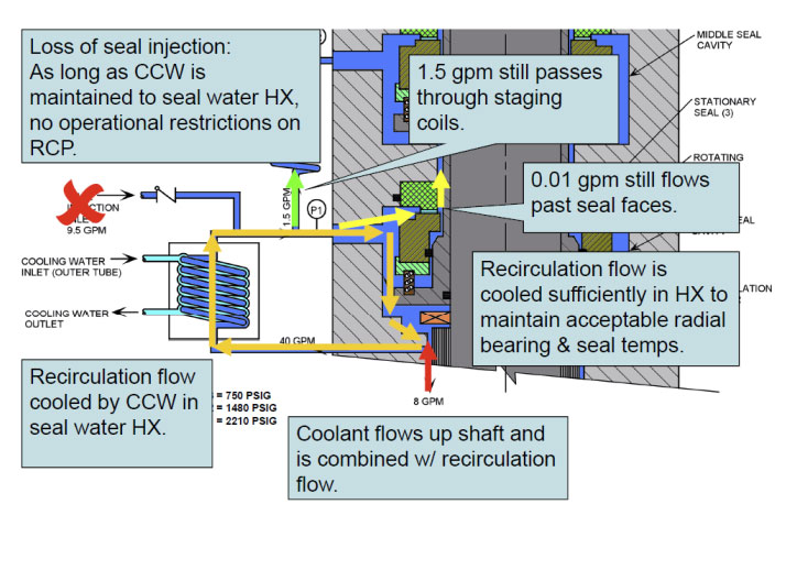
The above drawing shows the flow reversal that happens with a loss of SI flow. The NRC drawing has an error and an omission. The flow up into the seal area from the Reactor Coolant System is only equal to the sum of the last staging coil flow plus the top seal face leakage, ~1.5 GPM not 8 GPM as shown. Also the shown condition is totally dependent on the SR valve being open and it is not shown. The seal cooling conditions are correct if the SR valve is open. As the hot reactor coolant (~550 F) now flows upward into the seal, the CCW cooling in the thermal barrier area cools it (yellow arrows) to a temperature the seal can tolerate.
The below picture is one I made to show the configuration we were in right after the 1600 PSI SFAS signal closed the RCP SI and SR valves. It also explains why this is a concern to any Operator.
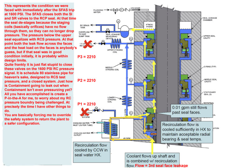
For all you folks who don’t understand why the seal de-stages and goes to Reactor Coolant System pressure when the SR valve is closed, try this at home. At a sink, get a small pencil-size stream of water running out of a faucet. The water knob is now the “staging coil” orifice, dropping the city water pressure to almost nothing (stick your finger under the flow). Now, your finger is going to become the SR flow isolation valve. Slowly push it up against the spout to stop the flow. Did you get wet? Why?
For everyone who thinks all this information on RCP seals is superfluous to TMI, I can assure you it is not. And I think every licensed nuke operator in the world will agree with me. When the crap hits the fan in the Control Room, and the event deviates from your training and procedures (as Murphy shows it can), almost every step an operator takes is done with this type of background information rapidly racing through his mind, for every task he/she has to perform to stabilize the plant; Immediate Operation Steps excepted. So when the group of Monday morning quarterbacks get in their assigned rooms and autopsy their assigned small piece-part of that event under a microscope, using expanded time scale data reports that I don’t have available to me in the control room, and then decide with their tunnel vision on just their assigned part concluding the Operator “should have known this or that”; I have news for you, I don’t have the luxury of working like that. I have to worry about all of it, but I can only do one thing at a time. My total training package an Emergency Procedures are going to define my priorities, not you. If you don’t like that, either change my training or you sign into the book and take over. But your conclusion for an Operator Error is not necessarily my error.
Extra Credit I couldn’t remember the GPM rating of DBNPP RCPs, so…
Q = m (delta T)
Where:
Q = rated thermal power of reactor in Mwt
m = mass flow rate of RCS in pounds/hr
= Specific heat of water at NOTP in BTU/pound mass-degree Fahrenheit
Delta T = Th – Tc in degrees F
Thus:
2772 Mwt = (X lb/hr) (1.35 BTU/lb- F) (608F – 556F)
Simplify:
2772 Mwt = X lb/hr (70.2 BTU/lb)
Convert Mwt to BTU/hr
~9458456607 BTU/hr = (X lb/hr) (70.2 BTU/lb)
Solve for X
X = 134,735,849 lb/hr. This is the required RCS flow rate from 4 RCPs at 100% power.
RCP capacity = (134,735,849 lb/hr)/4 = 33,683,926 lb/hr each RCP
Solve for nominal GPM/RCP @ STP
[33,683,926 lb/hr/(8.343 lb/gal @ STP) (60 min/hr)] [62.4 lb/ft-cubed @ STP/46.4 lb/ft-cubed @ NOPT]= ~90,500 GPM. I did remember it’s a big pump.